Project 1: Augmented Reality
Overview
In this project, I capture a video of a scene and use the camera calibration matrix to estimate the camera pose. Then, I use the camera pose to overlay a 3D model of a cube on the scene.
Setup
Capture a video that contains a box with regular patterns on it place in front of the camera.
Then use cv2.VideoCapture to read the video and plt.ginput to mark 20 points on the box.
The 20 points are used to estimate the camera pose.
Keypoints with known 3D world coordinates
We first marked 20 points on the box use plt.ginput and then set the 3D world coordinates of these points sicne we know the size of the box, and the patterns on the box are regular.
Due to some version conflicts, instead of using package skvideo.io, I use cv2.VideoCapture to read/write the video.
Propogating Keypoints to other Images in the Video
After that, we need to propogate the keypoints to other images in the video. I am using Off the Shelf Tracker cv2.TrackerMedianFlow_create() to track the keypoints.
Estimating Camera Pose
After tracking the keypoints, we can use least squares to estimate the camera pose. The camera projection matrix transforms the 3D world coordinates to 2D image coordinates. And the equation is given by: \[ s \begin{bmatrix} u \\ v \\ 1 \end{bmatrix} = K \begin{bmatrix} X \\ Y \\ Z \\ 1 \end{bmatrix} \tag{1} \] Simplify the equation, we get: \[ s \begin{bmatrix} u \\ v \\ 1 \end{bmatrix} = \begin{bmatrix} r_{11} & r_{12} & r_{13} & t_1 \\ r_{21} & r_{22} & r_{23} & t_2 \\ r_{31} & r_{32} & r_{33} & t_3 \end{bmatrix} \begin{bmatrix} X \\ Y \\ Z \\ 1 \end{bmatrix} \tag{2} \] We can use the equation to estimate the camera pose. To use the least squares method, rewrite the equation as: \[ A \begin{bmatrix} r_{11} \\ r_{12} \\ r_{13} \\ r_{21} \\ r_{22} \\ r_{23} \\ r_{31} \\ r_{32} \\ r_{33} \\ t_1 \\ t_2 \\ t_3 \end{bmatrix} = b \tag{3} \] Where A is a 2n x 12 matrix, and b is a 2n x 1 matrix. So, A martix is: \[ A = \begin{bmatrix} X & Y & Z & 1 & 0 & 0 & 0 & 0 & -uX & -uY & -uZ & -u \\ 0 & 0 & 0 & 0 & X & Y & Z & 1 & -vX & -vY & -vZ & -v \end{bmatrix} \]
Projecting a cube in the Scene
After estimating the camera pose, we can project a cube in the scene. The cube is defined by 8 vertices, and the edges are defined by the vertices. We can use the camera projection matrix to project the cube from 3D world coordinates to 2D image coordinates for each frame in the video.
Some improvements
The cube is not perfectly aligned with the box in the video. This is because the camera pose is not accurate enough. I improved the accuracy by using more keypoints, and filitering out the keypoints that are not reliable by teh distance between the keypoints in two consecutive frames. It looks better than beofre, but still not perfect. We can improve the accuracy by using more keypoints, or using a better tracker.
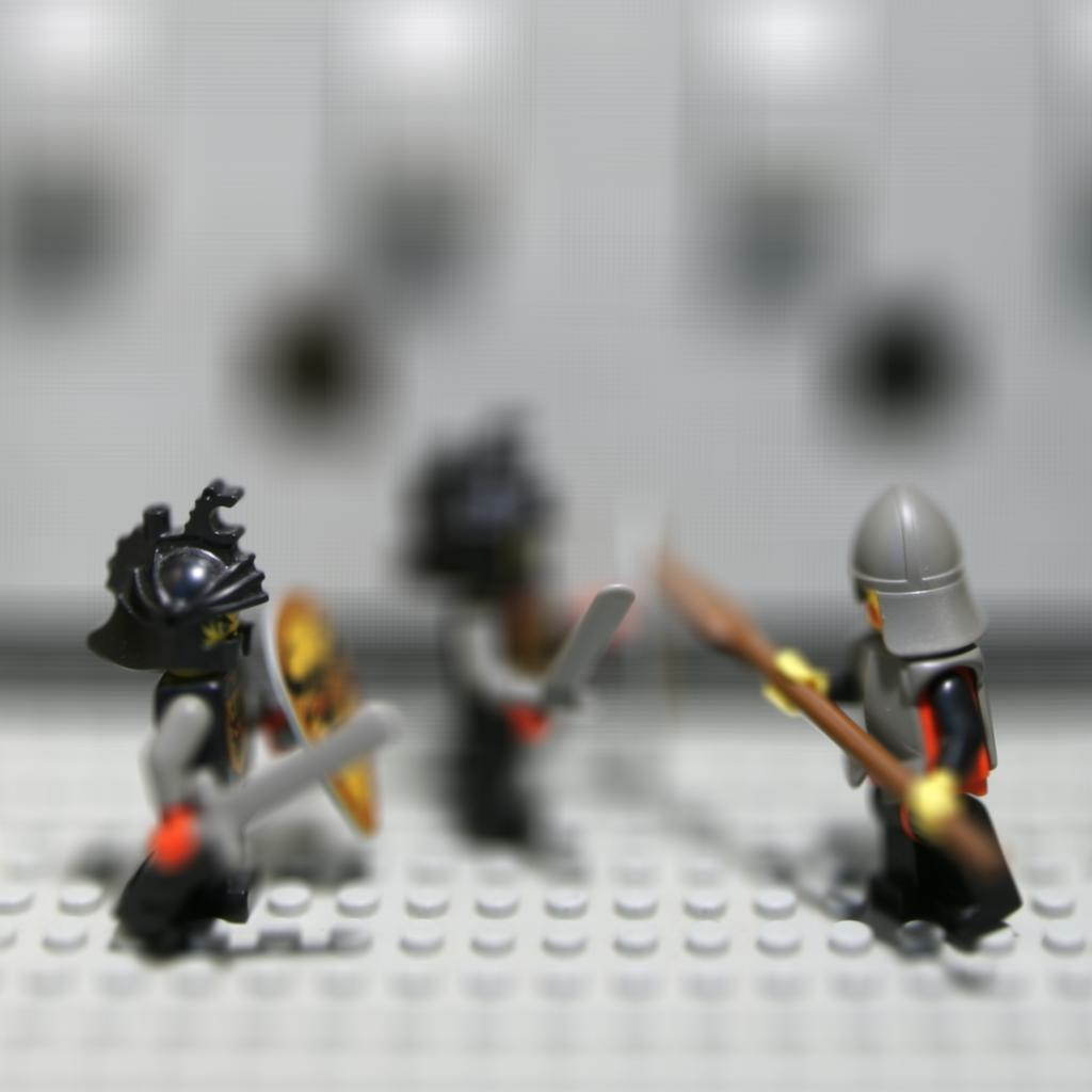
Project 2: Lightfield Camera
Depth Refocusing and Aperture Adjustment with Light Field Data
According to the paper "Light Field Photography with a Hand-Held Plenoptic Camera" by Ren Ng, the light field data can be used to refocus the image and adjust the aperture through simple operations. In this project, I use the light field data to refocus the image and adjust the aperture.
Setup
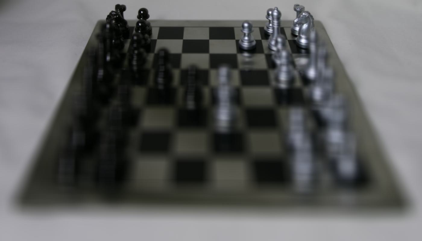
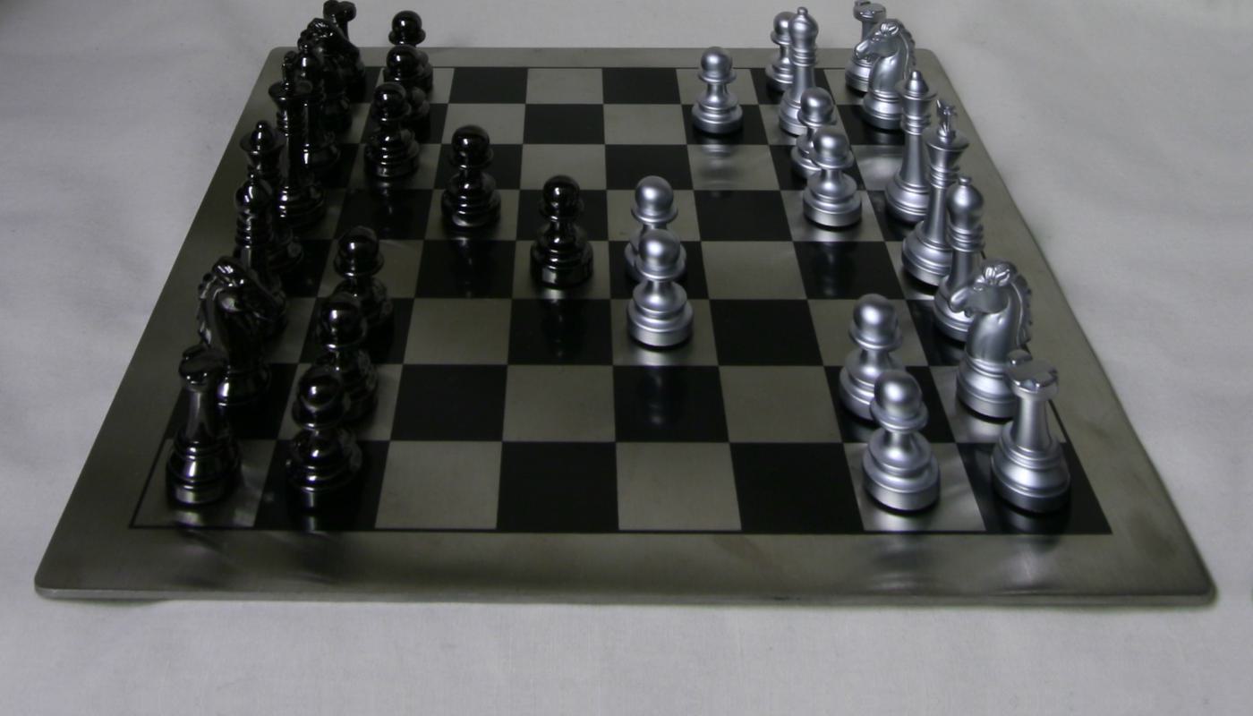
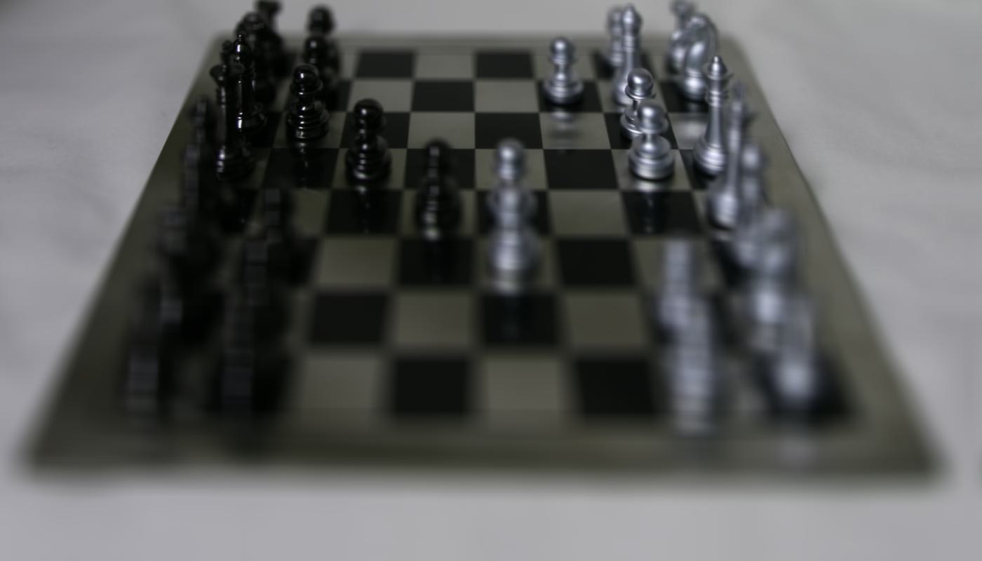
From the Standford Light Field Archive, I download the rectified light field data of the "Chess" and "Lego Knights" scene. Base on the img name, I can get the position of actual physical camera coordinates.
Depth Refocusing:
First, I only average all the images in the same scene which shows a image that are far focus, since the shift of the object is small if the object is far away.
So in order to get different focus in different depth, we need to shift the image in the light field data.
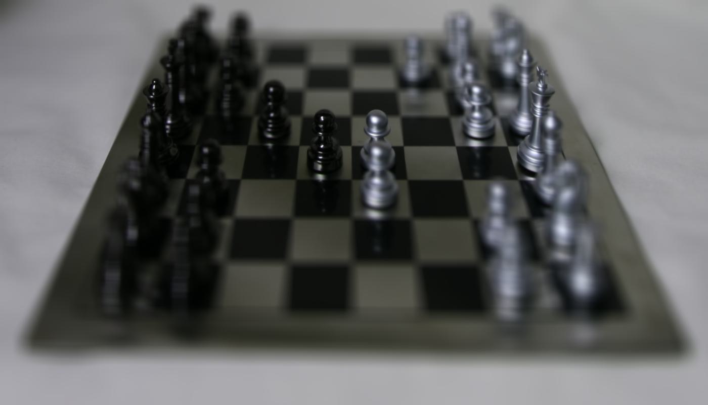
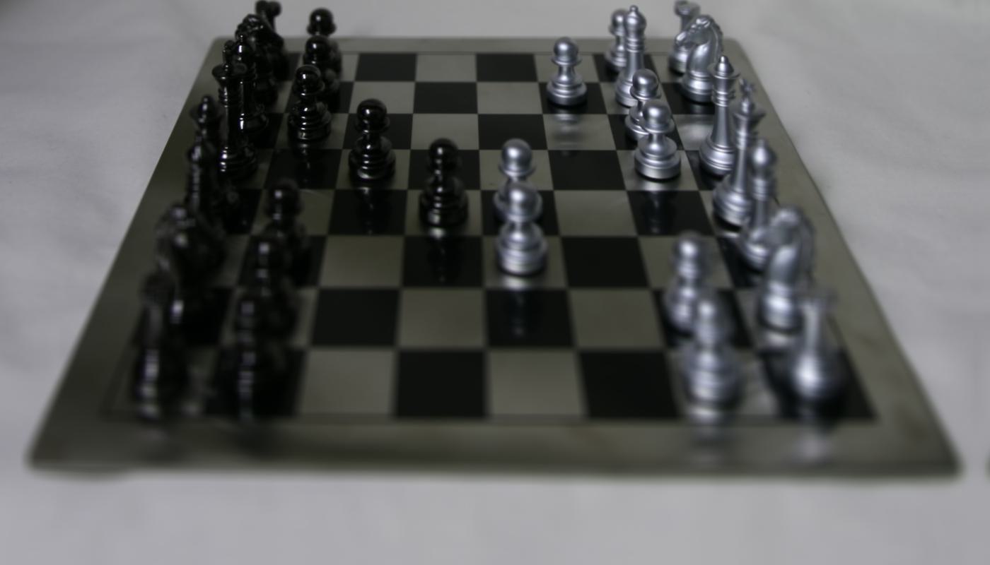
First, I selected a image as a center image, caculate the desired shift for x and y direction for each image in the light field data.
The desired shift is the different between the center image position and the image we want to shift and mutiply by a scale factor.
The larger the scale factor, the more the image will be shifted, the focus will be closer. and vice versa.
Then, I use the shift matrix to shift all other images to the center image by using the shift matrix(cv2.warpAffine).
After that, I average all the images in the same scene to get the refocused image.
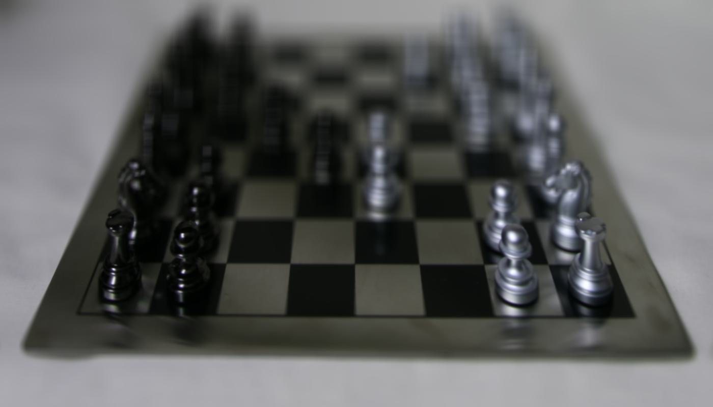


Aperture Adjustment:
The aperture adjustment is similar to the depth refocusing. The only difference is that for different aperture, we will use different amount of images to average. The larger the aperture, the more images we will use to average, and the more blur the image will be. To increase the DoF, we need to limit the number of images we use to average, and the shift of the image should be small. In other words, base on different aperture, I filiter out the images that are not in the range of the aperture, and then average the rest images.
Output for different aperture:
Bells & Whistle!
Interactive Refocusing: I also implement a interactive refocusing function, which allows user to click on the image to refocus the image. The image will be refocused to the point where the user clicked. Basically, I use the same method as the depth refocusing, but use ginput to get the user click position, and then base on the click position to calculate the shift matrix.